Modify
a Roland MC-202 MicroComposer to Achieve a High-rate LFO (Similar to
the Novamod for the SH-101)
My
MC-202 is a mess. It
looks like
crap on the outside, with holes bored in its hull and paint
in places where it shouldn't be. In fact, I may even come
down
with a small case of cancer due to all of the fancy metallic
spray-paint I used.
The
inside is another story:
it's a jungle of tenuously attached wire thanks to my
not-exactly-standard soldering techniques.
Hey,
what do you expect with my first major electronics project?
Despite
its cyberpunk exterior and unprofessional insides, this MC-202 makes
some noises no other Roland synth can.
Here's
what I've done to it, so far:
Upgraded CV/Gate jacks (bypasses the CPU
quantization effect)
VCF CV IN
Audio IN (to VCF)
Pulse OSC OUT
Sub OSC OUT
Mod CV IN (I think; it doesn't exactly do what's expected)
"Hidden" TRI OSC to Mixer with pot
Normal/High-rate LFO switch
In
general, the idea of modding things stems
from an AFX interview I read a long time ago ('93 or so), where he
stated he modified most of his gear, specifically his 101.
The
actual impetus for the project was this site: http://www.cykong.com/Synths/Roland%20MC-202/RolandMC-202.htm.
Cy describes every mod he performed in great detail.
I
don't think he intended his site to be an instructional guide,
but
the descriptions were so good that, I, a person who had never picked up
a soldering iron before this project, was able to complete 90% of the
mods shown.
The one mod that Cy didn't
do that seemed
interesting to me was a high-rate (audio domain) LFO mod, like the one
found on the Novamod for the SH-101.
What capacitor to change?
What resistor
to take off? How the hell should I know? Did anyone
know?
The answer was "yes".
Someone on the Yahoo! SH-101
group pointed to
the chip that produces the LFO and the capacitor that I would need to
switch if I wanted to produce a hyperspeed LFO. However,
since I
knew the signal flow of the LFO, I knew that removing the resistor (R8)
would accomplish a similar result. Since the LFO mod on the
Novamod recommends "jumping" the resistor, that's the path I took.
The results are pretty good.
Listen to a mp3 of the modification.
Run-down:
:00-:17 -- short, percussive loop
demonstrating high speed LFO->VCF
:18-:36 -- LFO->pitch
modulation
:37-1:03 -- standard electro sequence
1:04-1:58 -- LFO->PW, then
LFO->pitch, filter, both, all
1:59-3:14 -- acid loop with accent
and portamento; LFO modulates filter; LFO amp is raised; pitch is raised
3:15-end -- a sustaining sound where
the LFO is modulating the filter and pitch; LFO amp is swept up, then
down
Another
sound file, here.
So, how do you do it? Take a read and view the pics:
First of all, don't try
this--at all--unless
you're experienced electronics-guy, like me (forget what you read in
the paragraphs, above). I cannot be held responsible for
anything
that goes wrong, but deserve all the credit if anything goes right.
Again, these pictures and words are for entertainment
purposes
only and not to be used as a guide or anything that remotely resembles
a set of instructions on how to do things.
Preliminary
steps:
0.1 Decide if you want a switch (SPDT) to select normal or high-speed
mode
0.2 Find a place to put the switch
0.3 Get your soldering iron and three pieces of wire ready
Here we go:
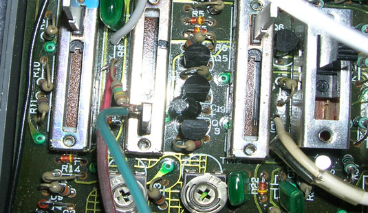
1. Open the 202
2. Locate resistor R8 (right below capacitor C1, between the rate and
delay sliders)
3. Flip the circuit board over and find the holes that correspond to R8
4. De-solder the first leg of resistor R8 (the one closest to C1)
5. Flip the circuit board back over and gently lift the top-most
(again, closest to C1) side of R8
6. You should now have a hole where the one leg of R8 once stood
7. Wire your switch, thusly: the middle wire should be the "common"
connection that will go in the now-vacant R8 hole; solder the other
wires to the other legs of the switch [below: white is common, red will
go after the resistor, green will go on to the resistor]
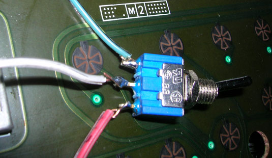
8. Now that the switch
is wired, solder the common connection to the R8
hole (you'll have to flip the board to solder it on the solder side)
9. Solder one wire to the end of R8 (you may have to bend it straight
up to have enough room to maneuver your iron)
10. Solder the other wire to the hole of the second leg of R8 (yes,
just poke it through and solder on the other side)
11. Place the switch in the hole you drilled for it (you did drill a
hole, didn't you?!?), and tuck the wires away, neatly [below]
12. Close
the lid and experiment
Did it work? Cool.
I'm glad it did.
::Go
back to
glitched.org and listen to some trax
||all
content ©2006
[d]/glitched.org ::updated 050506||
